Automotive Parts Molds are the hidden tools behind dashboards, grilles, door panels, lighting housings, and under-hood components. They shape molten plastic or metal into repeatable parts. Their work seems simple from the outside. It is not.
“The mold is the heart of the injection molding process,” writes John P. Beaumont, a respected mold-design author and injection-molding specialist. His statement explains why mold quality affects far more than appearance. It influences dimensional accuracy, cycle time, surface finish, material flow, and production waste. A small error near a gate can create weld lines, sink marks, or uneven filling across a visible panel.
This article will explain what Automotive Parts Molds are and how manufacturers make them. The process usually begins with product data, draft analysis, parting-line planning, and material selection. Engineers then design cavities, cores, runners, cooling channels, ejectors, and slides. Skilled machinists cut these details into steel or aluminum using milling, turning, electrical discharge machining, and precision polishing.
The process is highly controlled.
Yet it is not perfectly linear.
A mold may pass an initial design review and still require changes after the first trial. Heat distortion, trapped air, or difficult ejection can reveal problems that software missed. That reality deserves attention. Reliable mold making depends on testing, measurement, documentation, and experienced judgment. It also requires honest communication between designers, toolmakers, material suppliers, and automotive manufacturers. The goal is not merely to produce one acceptable part. It is to create a durable tool that performs consistently across thousands of production cycles.
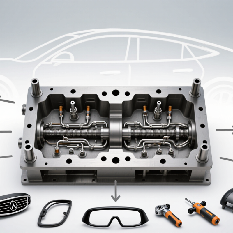
An automotive parts mold is a precision tool that shapes plastic, rubber, or metal into repeatable vehicle components. It contains a cavity and a core, which create the part’s outer and inner surfaces. During production, heated material enters the mold under controlled pressure. After cooling, ejector pins release the finished component.
Mold design depends on the part’s function, size, material, and expected production volume. Engineers study wall thickness, draft angles, cooling channels, and possible deformation before machining hardened steel or aluminum. Skilled technicians then polish critical surfaces and check dimensions with calibrated measuring equipment. Small errors can cause flash, sink marks, or difficult assembly. In practice, even a well-designed mold may need adjustment after its first trial. That is normal, but it should be documented carefully.
Tips: Keep cooling channels balanced. Inspect vents regularly. Record every mold change.
A reliable automotive parts mold also requires controlled testing. Technicians inspect sample parts, compare them with approved drawings, and monitor cycle times. They may modify the gate, adjust pressure, or improve ejection after testing. Material shrinkage can be difficult to predict perfectly, especially around ribs and thick sections. This is where production experience matters. The mold must deliver consistent parts, not merely one attractive sample.
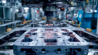
An automotive parts mold is a precision tool that shapes dashboards, grilles, clips, and structural plastic components. Its cavity defines every visible edge. Its steel must resist pressure, heat, and repeated clamping. Grand View Research estimated the global automotive plastics market at about US$51.7 billion in 2023. The report forecasts approximately 4.2% annual growth through 2030.
Toolmakers commonly select P20 pre-hardened steel for general injection molds. H13 steel suits hotter processing and frequent production cycles. Stainless steel helps when moisture or corrosive additives threaten the cavity surface.
Aluminum remains useful for prototypes and short runs because it cuts faster and transfers heat efficiently. Still, aluminum can wear sooner. That trade-off is easy to underestimate.
Design decisions often matter more than material grades. Proper draft angles release parts without scuffing polished surfaces. Deep ribs need careful thickness control, or sink marks may appear like shallow dents. Conformal cooling channels can shorten cycle times and improve temperature balance. Interchangeable inserts also simplify repairs around grille openings and fastening points.
OICA reported roughly 75.5 million motor vehicles produced worldwide in 2024. That volume demands repeatable molds, not merely attractive first samples. A perfect CAD model can still fail beside a real press. Warpage, trapped air, and uneven cooling deserve physical testing.
Automotive parts molds begin with product intent, not steel selection. Engineers study the part’s function, appearance zones, tolerances, and expected production volume. A dashboard trim needs controlled texture, while a structural bracket demands reliable dimensional stability. The team converts these requirements into a manufacturable 3D model. Parting lines, draft angles, wall thickness, ribs, and undercuts receive careful review. Small changes matter.
Flow simulation helps predict hesitation, weld lines, air traps, and uneven filling. Engineers adjust gate locations and runner sizes before cutting metal. They also estimate material shrinkage, because cooling plastic rarely follows the nominal CAD shape. This step is useful, but not perfect. Simulation depends on accurate material data and realistic processing conditions. A clean screen cannot replace practical judgment.
Mold construction is then planned around core and cavity strength, cooling channels, slides, lifters, and ejection points. Cooling should reach thick sections evenly, or the finished part may warp near its mounting holes. Toolmakers check machining access and polish requirements before finalizing the design. Prototype trials expose issues that drawings can hide. Flash, short shots, or difficult ejection may require steel changes. Experienced teams record these findings and revise the mold rather than blaming the operator. Even a proven design deserves another review when resin, cycle time, or part geometry changes.
| Design and Engineering Dimension | Typical Data or Requirement | Why It Matters in Mold Development |
|---|---|---|
| Mold Function | Forms plastic, rubber, or lightweight composite automotive components with repeatable geometry. | The function determines the mold structure, tooling material, cooling method, ejection system, and expected service life. |
| Common Molded Parts | Interior trim, instrument-panel components, door panels, grilles, brackets, bezels, housings, clips, and under-hood covers. | Part size, visible surfaces, assembly interfaces, and functional loads influence the mold layout and manufacturing method. |
| Design Input | 3D CAD model, 2D drawing, material specification, product tolerances, appearance requirements, and production volume. | Complete and accurate input data reduces redesign, machining changes, and dimensional nonconformity. |
| Parting Line | Placed along a suitable transition in the part geometry to separate mold halves with minimal visible mismatch. | A well-positioned parting line improves appearance, simplifies machining, and helps prevent flash and difficult ejection. |
| Draft Angle | Often approximately 0.5°–2° for many molded surfaces; textured or deep surfaces may require more. | Draft allows the molded part to release without scuffing, deformation, or excessive ejector force. |
| Wall Thickness | Designed as uniformly as practical; many automotive thermoplastic parts use approximately 2–4 mm, depending on resin and structure. | Consistent thickness helps control shrinkage, sink marks, warpage, filling behavior, and cycle time. |
| Shrinkage Compensation | Tool dimensions are adjusted using the material supplier's validated molding-shrinkage data; actual values vary by resin, fiber content, flow direction, and process conditions. | Correct compensation helps the finished part meet dimensional and assembly requirements after cooling. |
| Mold Material | Common choices include pre-hardened or hardened tool steels; aluminum may be used for selected low-volume or prototype applications. | Material selection balances wear resistance, corrosion resistance, thermal conductivity, machinability, cost, and expected shot life. |
| Cavity and Core Layout | Single-cavity, two-cavity, or multi-cavity layouts are selected according to part size, machine capacity, output target, and tooling budget. | The layout affects productivity, balance, mold size, filling consistency, maintenance, and total manufacturing cost. |
| Gate Design | Gate type and location are selected according to material flow, wall thickness, appearance, weld-line position, and trimming requirements. | Proper gating improves filling, reduces cosmetic defects, and supports stable packing and dimensional control. |
| Runner System | Cold runners or hot-runner systems may be used; runner dimensions are determined through flow analysis and process requirements. | The runner system controls melt distribution, pressure loss, material waste, cycle performance, and gate quality. |
| Cooling System | Cooling channels are positioned near heat-intensive areas while maintaining sufficient steel thickness and structural strength. | Balanced cooling reduces cycle time and minimizes warpage, residual stress, and uneven shrinkage. |
| Venting | Vents are placed near flow ends, weld-line areas, and potential air traps; vent dimensions depend on the molding material and process. | Effective venting prevents burn marks, short shots, trapped air, and inconsistent surface quality. |
| Ejection System | Ejector pins, sleeves, lifters, stripper plates, or air ejection may be used according to part geometry and release direction. | The system must remove the part evenly without leaving unacceptable marks, distortion, or stress whitening. |
| Mold-Flow Analysis | Digital analysis evaluates filling pattern, pressure, cooling, weld lines, air traps, shrinkage, and predicted warpage. | Simulation identifies design risks before steel cutting and supports evidence-based gate and cooling decisions. |
| Machining and Fabrication | Typical operations include CNC milling, drilling, electrical-discharge machining, grinding, polishing, fitting, and surface treatment. | Each operation contributes to dimensional accuracy, surface finish, wear resistance, and correct movement of mold components. |
| Surface Finish | Finishes may range from machined textures to polishing or controlled texturing, depending on the visible surface specification. | Surface condition affects appearance, part release, texture transfer, friction, and the visibility of molding defects. |
| Trial Molding | Initial trials verify filling, packing, cooling, ejection, cycle stability, appearance, and part dimensions. | Trial results reveal practical issues that may not be visible in CAD or simulation, allowing controlled tooling adjustments. |
| Dimensional Validation | Inspection may include coordinate measurement, gauge checks, scanning, material verification, and assembly-fit testing. | Validation confirms that the molded part matches drawing tolerances and interfaces correctly with related components. |
| Production Readiness | Approved process settings, maintenance instructions, spare-part lists, inspection standards, and change records are documented. | Standardized documentation supports repeatable production, faster troubleshooting, and consistent mold performance. |
| Maintenance Considerations | Routine work includes cleaning vents, inspecting gates and ejectors, checking cooling passages, lubricating moving parts, and monitoring wear. | Preventive maintenance preserves part quality, reduces unplanned downtime, and extends useful tooling life. |
An automotive parts mold is a precision tool that shapes plastic or metal components repeatedly. For plastic parts, engineers begin by defining geometry, material, shrinkage, tolerances, and expected production volume. The U.S. Department of Energy reports that a 10% vehicle weight reduction can improve fuel economy by roughly 6–8% under comparable conditions. That pressure makes accurate, lightweight components increasingly important.
The mold design is developed in CAD, then checked with filling, cooling, and warpage simulations. Engineers select tool steel or aluminum based on cycle volume, heat, and maintenance needs. CNC machining creates the main cavities, while electrical discharge machining forms deep ribs and sharp details. Cooling channels are drilled around the cavity. Small changes matter here. A one-degree corner can affect release and surface quality.
After machining, technicians polish, texture, assemble, and measure the mold. A trial shot follows. Operators inspect flash, sink marks, weld lines, and dimensional errors. A first trial often exposes assumptions that looked sound in CAD. Corrections may require steel removal, insert replacement, or revised cooling. The IEA’s Global EV Outlook 2024 reported more than 14 million electric cars sold globally in 2023, increasing demand for precise battery, interior, and structural components. Still, speed should not replace verification. Process records, dimensional reports, and controlled revisions help keep every approved mold traceable.
A finished automotive parts mold is not ready for production after machining alone. Technicians inspect the cavity, core, ejector pins, slides, and cooling channels. They measure critical dimensions against approved drawings. A trial run follows. The team checks filling, part weight, surface texture, warping, and release performance. Short shots can reveal poor venting or uneven pressure. These defects often appear near ribs, corners, and deep pockets. Pressure and temperature records provide useful evidence. We record every result. Still, no test catches every weakness.
Tips: Keep a clear inspection checklist. Use calibrated measuring tools. Photograph unusual marks before adjustments. Do not trust appearance alone. Small errors can grow quickly.
After approval, maintenance begins with each production cycle. Operators clean resin residue from parting surfaces and vents. They inspect moving components for wear, scratches, or unusual noise. Lubricant must match the mold material and operating conditions. Cooling channels need periodic flushing because scale reduces heat transfer. If water flow changes, production staff should investigate immediately. Storage also matters; the mold should be dry, protected, and supported correctly. In practice, maintenance schedules are sometimes too optimistic. A real production record may justify shorter intervals. That extra check can prevent expensive dimensional drift and unexpected downtime.